A battery-based solar system enhances your electricity offset through solar. This system generates 25% more power as compared to conventional solar installation. Depending on the customer, a battery-based system can be of 2 types; a system with only batteries (off-grid), and a system with net-metering (hybrid system).
It is important to size your battery because energy input for the corresponding facility depends on the battery’s ability to discharge power in case of backup, bad weather, or any other factor which limits the panel array generation. Proper battery sizing is essential to ensure that excessive batteries are not used, saving costs. There are 4 main steps involved in sizing a solar battery plant.
1) CALCULATION OF ENERGY CONSUMPTION
- INVERTER SIZE:
For the determination of battery size, the total wattage of the facility is measured. Power inputs of all the loads connected are summed up. These loads can be anything ranging from fans & lights to storage rooms & manufacturing machines. Some appliances intake more than their rated power during operations. Therefore, the surge rating of the inverter should cover these temporary fluctuations.
EXAMPLE:
A house comprising 2 fans of 75 W each, 1 AC of 3000 W & 4 tube lights of 25 W each, would require an inverter size of 3 KW.
- DAILY ENERGY USE:
This refers to the total energy used in a day by the facility. To calculate this, the total hours of usage for each load are calculated & multiplied by the wattage of that load. This is summated & multiplied by 1.5 to accommodate possible power loss. EXAMPLE:
Fans, AC & tube lights mentioned in the above example operate for 8, 2 & 10 hours respectively, then the total watt-hours
= (2*75*8) + (1*3000*2) + (4*25*10) = (8200*1.5) = 12300 watt-hours (Wh)
- DAYS OF AUTONOMY:
Days of autonomy refers to the number of days that no power generation is possible. This can be due to factors like bad weather, high levels of shade, etc. This factor is essential to measure how much energy can be consumed when no new energy is being generated. Generally, the sun powers the solar system for 5-6 hours. But a system may have to run for 24 hours a day. This number is taken as 2,3 or 4 usually.
EXAMPLE:
Two days of autonomy means that your battery system is capable of providing energy for 48 hours without charging.
- BATTERY BANK CAPACITY:
The number of watt-hours per day is multiplied by the number of days of autonomy calculated earlier. It helps in determining the capacity of the battery bank for managing energy demands, during the ‘no generation period, without charging the battery. This number is usually 50% of the Depth of Discharge, so it is multiplied by 2 & divided by battery voltage (12, 24, or 48 for commercial systems) to get the capacity in ampere-hours (Ah) format.
EXAMPLE:
12300 Wh (daily energy use)*2 days (autonomy days) = 24.6 kWh
24600 kWh/48 V (battery voltage) = 512.5 Ah
This number divided by the battery rating estimates the number of batteries required to complete the system.
2) ESTIMATION OF OPTIMUM MPPT CHARGE CONTROLLER
The solar charge controller monitors the voltage of the battery. When the battery voltage reaches the threshold level, it opens the circuit and the charging of the battery from the panels stops. Optimum charge controllers are also important because it blocks the reverse current from flowing back to the solar panels.
To calculate the maximum current through the controller, we take the power produced by the solar array & divide it by the battery voltage.
EXAMPLE:
Suppose for the loads mentioned above, the solar array produces 5 KW of power. Using the power = current*voltage formula, we estimate the maximum current; 5000/48 = 104.16. Therefore, we can either use a single-charge controller of M104 value or 2 charge controllers that summate to 104 amperes.
3) BATTERY CONNECTIONS
The important difference between wiring panels in series or parallel is that it affects the voltage and amperage of the resultant circuit. It is critical in deciding the string layout of solar arrays, to achieve the optimum voltage & Ah that we calculated during electricity consumption.
- SERIES (voltage is added, the current is not added)
Series connections are mostly used for MPPT controllers because these can accept a higher voltage input, and still be able to charge your 12V or more batteries.If batteries are connected in series, the voltage adds up. For example, if you connect two of 24 V batteries in series, it would mean that you have a 48 V system, maintaining the same amperage.
- PARALLEL (current is added, voltage is not added)
In the case of an inverter working with a low input voltage, the modules can be connected in parallel to the inverter by connecting the batteries in parallel, we can increase the system capacity. If you are using a 48 V, 92 Ah battery. Connecting two of those batteries would mean that you still have a 48 V system, however, your battery capacity has been increased to 184 Ah.
4) BOS (Balance of Structure)
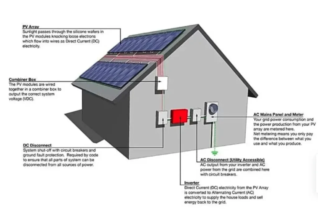
- SAFETY DISCONNECTS
A solar PV system typically has two safety disconnects. The 1st is the PV disconnect (or Array DC Disconnect). The PV disconnect allows the DC between the modules (source) to be interrupted before reaching the inverter.
The 2nd disconnect is the AC Disconnect. The AC Disconnect is used to separate the inverter from the electrical grid. In a solar PV system, the AC Disconnect is usually mounted to the wall between the inverter and the utility meter. The AC disconnect may be a breaker on a service panel or it may be a stand-alone switch.
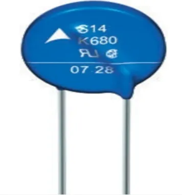
- SURGE PROTECTION
Solar panels are especially prone to lightning strikes due to their large surface area and placement in exposed locations, such as on rooftops or ground-mounted in open spaces.
A surge protector helps prevent damage to electronics by diverting the extra electricity from the power line into the grounding wire. In most common surge protectors, this is achieved through a metal oxide varistor (MOV), a piece of metal oxide joined to the power and grounding lines by two semiconductors.
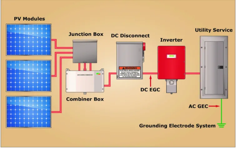
- GROUNDING EQUIPMENT
Regardless of system voltage, equipment grounding is required on all PV systems. Appropriate bonding and equipment grounding limit the voltage imposed on a system by lightning, line surges, and unintentional contact with higher-voltage lines. It also limits the voltage-to-ground that can occur on normally non-current-carrying metal components, ranging from frames and rails to conduits and enclosures.
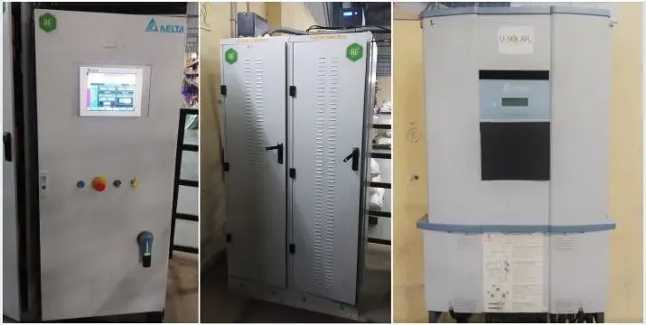
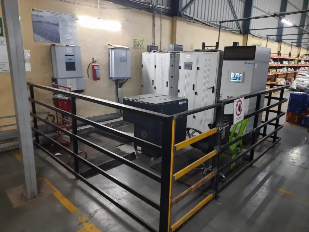
- POWER CONDITIONING
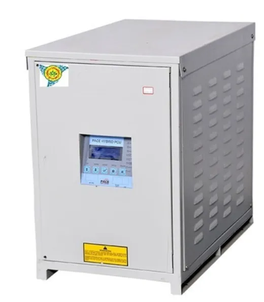
Solar Power Conditioning unit (PCU) is an integrated system consisting of a solar charge controller, inverter, and Grid charger. It provides the facility to charge the battery bank through either a Solar or Grid/DG set.
PCU automatically transfers the load to the Grid/DG power and also charges it simultaneously. It controls the solar power use & uses Grid/DG power only when the solar power/battery charger is unable to meet the load requirement.
__________________________
If you are looking to adopt solar, please feel free to get in touch with us. We believe in partnering with our clients on their sustainability journey.
Email us at info@usolar.in
WhatsApp us at +916366226970 | https://wa.me/916366236970